Game Boy Link Cable Breakout Board
I have been thinking about interfacing with my Game Boy for a while via the link cable but had no way, other than destroying a cable, to connect to it.
Eventually I stumbled upon a blog post where someone had written about creating a link cable breakout board. Unfortunately they didn’t distribute their CAD files but I figured now would be a good time for me to learn how to create my own PCBs as it’s something I’ve never even attempted before.
I did some research to find out what software is best to use and found people seem to be split between Eagle and KiCAD, at least for hobby use. I ended up using KiCAD as I’ll try to take the open source route if it’s available. Having never used any software like this before I did some more research and found a really great video series called “Getting to Blinky” which follows the full process of PCB design with KiCAD and covered all the things I thought I’d need to do. While making my own design I often returned to these videos for some quick reference which was great.
The board I wanted to make would just be cut to size to fit inside the Game Boy link cable, have 3 pads either side for the cable to connect to and expose 6 contacts for me to connect to some kind of device. This made for a VERY simple schematic as there aren’t really any components other than the two connections.
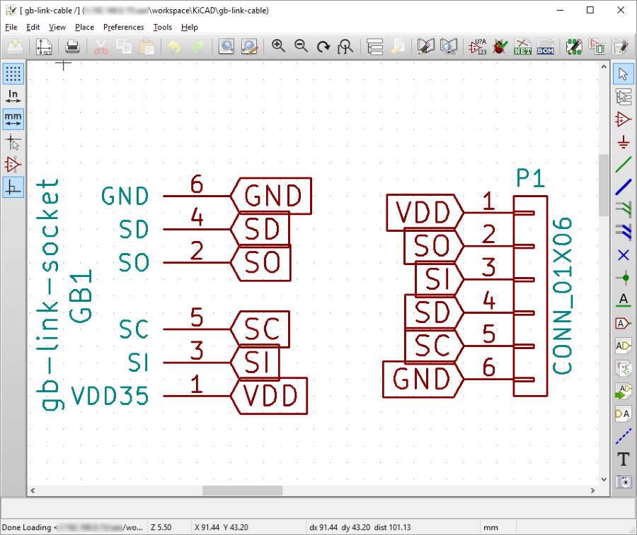
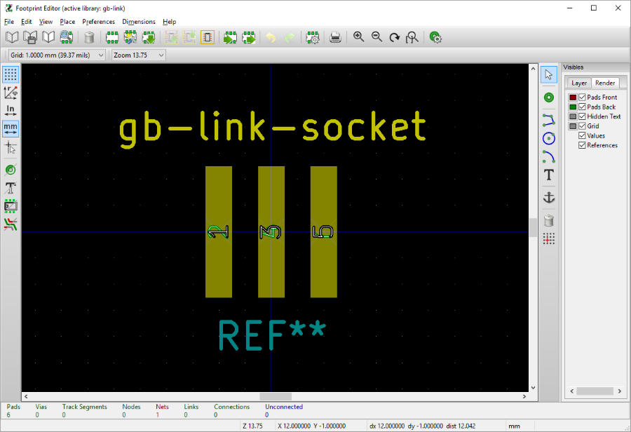
On the right CONN_01x06 is a pre-defined 1x6 pin through-hole connector in KiCAD, the left is a custom component I created for the Game Boy link cable. Below is the custom footprint created with 1mm wide by 5mm long pads spaced 1mm apart front and back for each of the link cable wires to connect to via the socket on the end of the cable.
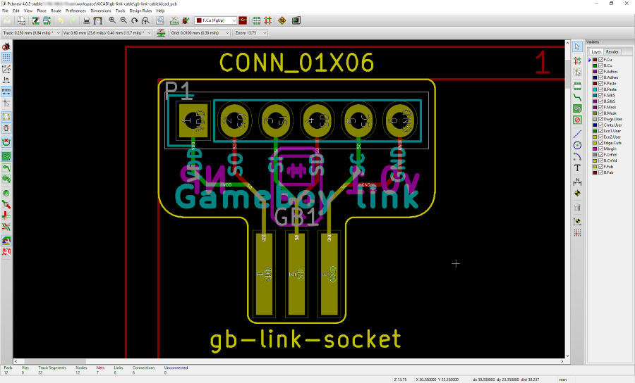
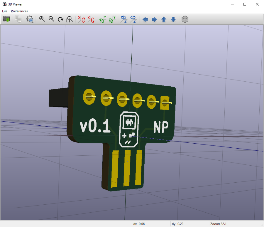
Once the schematic was finished, which didn’t take long, the next step was the PCB design itself. Below is a screenshot of the final PCB I created. The gb-link-socket gets a 0.5mm padding making the PCB cutout around it 6mm wide, which is the interior size of the link cable socket that I measured with some calipers. Other than that I spent most of my time on the silk screen layer attempting to draw a tiny Game Boy on the back side of the board.
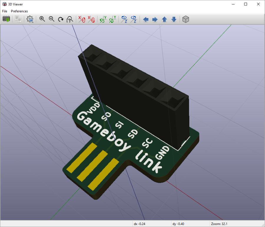
With the board designed I used KiCADs excellent in-built 3D viewer to preview the board and see that it looked as I expected. I really didn’t want to order some boards only to find out the pins were the wrong way up or the 1x6 connector would hang off the edges. Thankfully the preview looked good to me so it was time to find somewhere to have them made.
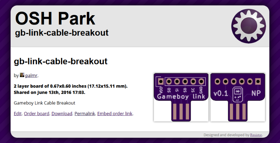
I attempted to find somewhere local in London, or at least in the UK, that would let me upload the Gerber files that I generated from KiCAD and just create the boards and send them to me. Unfortunately I couldn’t find anywhere that was reasonably priced, suitable for small-volume runs or that had a confidence-inspiring upload process. Thankfully I found OSH Park which is a community PCB fab who take many community designs and have them made all on one large board before cutting them apart which keeps the price low. For 3 of my boards they charged me an astonishingly reasonable $2. Including international delivery. Not only that but they let people share their designs on their website for others to order, so if you want a Game Boy link cable breakout board you can order mine from OSH Park today!
You can also check out my KiCAD files which I uploaded to GitHub if you want to customise or alter the board: https://github.com/Palmr/gb-link-cable
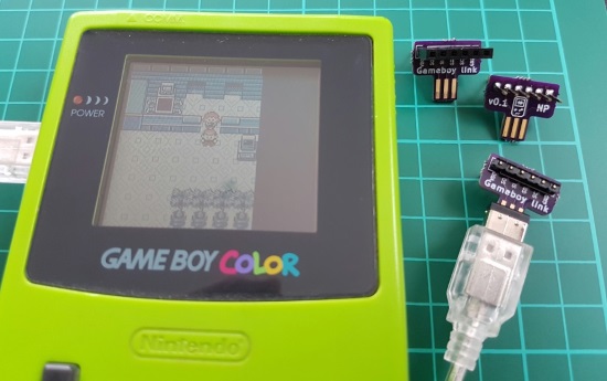
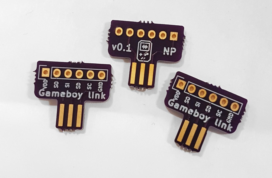
After a couple of weeks they arrived with a sticker, conforming to the Open Sticker Standard which is a thing, and here they are straight out of the packet on my desk at work looking very shiny and new. And purple. Once I got them home I soldered a variety of different (male, male and female and double-sided male) 1x6 pin connectors to the boards to try them out in different ways. You can see a photo of them soldered at the top of this post with one of them fitting perfectly into the link cable first time.
Now with these boards I quickly created a custom Game Boy ROM using GBDK to send/receive data over the link cable and flashed that to my original Game Boy flashcart (using my modified flasher) to test out the board. I might post more details on the ROM and flashing in a future post should I make anything of note using this board but for now it’s not important.
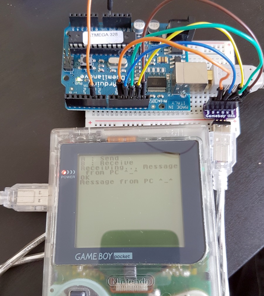
After a brief attempt manually bit-banging the Game Boy with a pair of wires by hand to little success (damn you switch bounce!) I then wrote a little bit of code for my 2009-era Arduino that would read data from my PC over serial and send it out to the Game Boy.
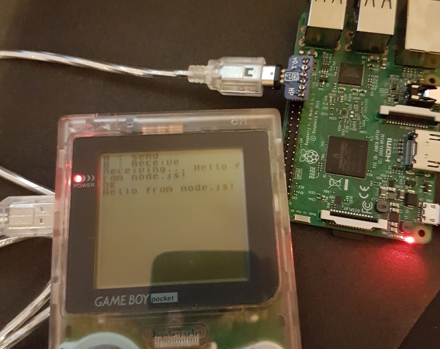
But that is an electronics project these days unless you’re using a Raspberry Pi. I happened to have a Model 3 handy with the larger GPIO than my original version and it just so happens there’s one position (GPIO pins 29-39) which lines up perfectly with the female 1x6 pin header I soldered to one of the boards. I then used the obvious language of choice for this kind of project: Javascript.
Now I’ve checked I can send messages to/from an Arduino and the Raspberry Pi my next plans are to investigate the first generation Pokémon link cable protocol to see if I can use the Raspberry Pi to play over the internet or look at writing better custom ROMs that can do more than show ASCII messages. If you have any project ideas, let me know.